fig8

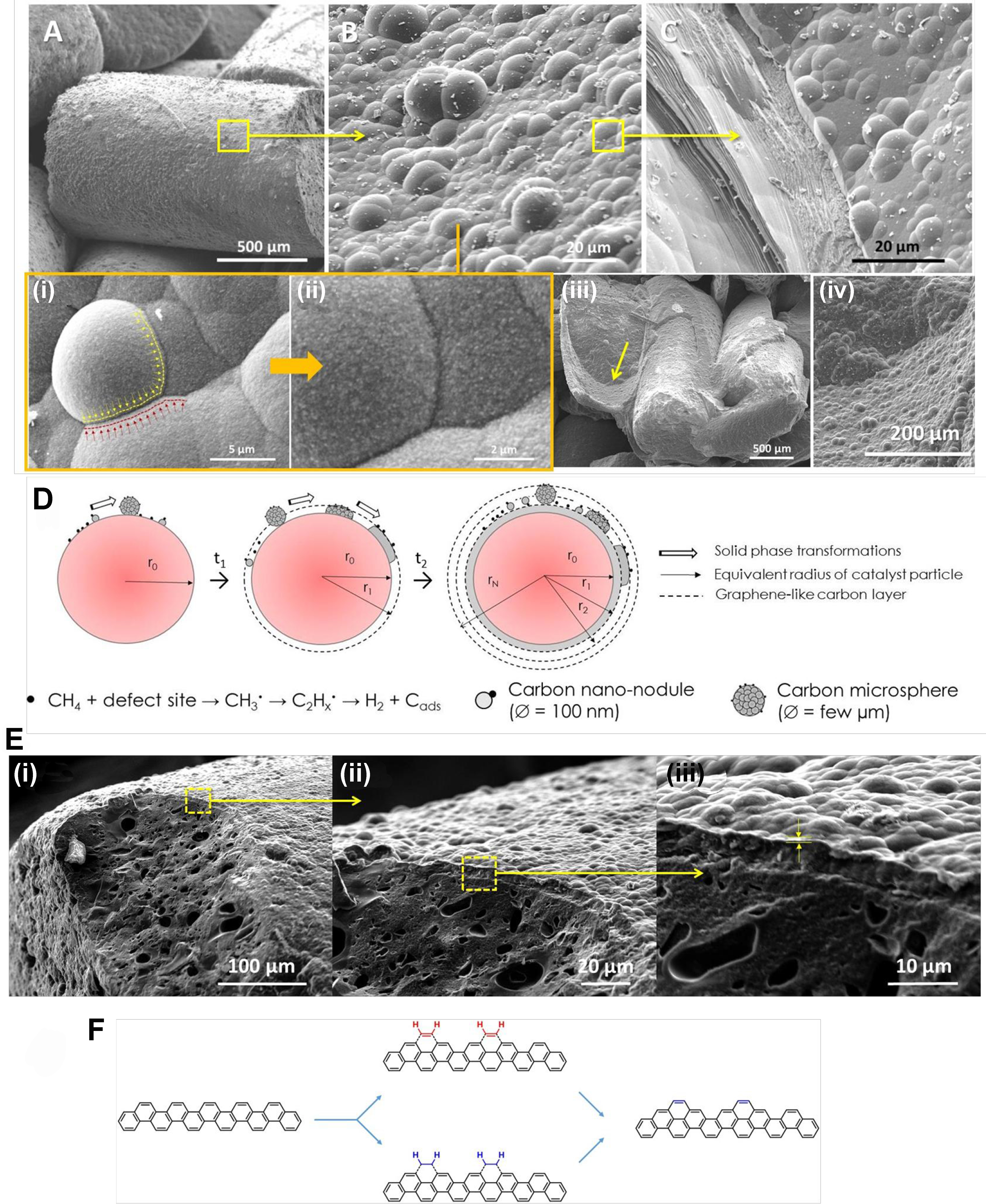
Figure 8. (A-C) SEM micrographs of the spent IH sample (R1) showing the microstructure modification of deposited graphitic compounds: low magnification imaging of deposited graphitic layer, medium resolution imaging of the graphitic nodules and flat graphene sheets structure. [B(i)] Detail imaging of the graphitic nodule flattening. [B(ii)] High-resolution SEM micrograph of the carbon nanoparticles (100 nm) that constitute the graphitic nodules. [B(iii) and (iv)] SEM micrographs showing the inner section of the as-deposited carbon with similar structure as that deposited on the top surface of the spent catalyst; (D) The schematic representation of the growth of the carbon layer by adsorption, coagulation and flattening of gaseous reactants to generate a coating carbon layer; [E(i)-(iii)] SEM micrographs with different magnifications showing the detailed microstructure of the graphene-like layer with bubbling shape deposited on the spent catalyst surface; (F) Schematic representation of the C2H2 incorporation on the armchair according to the CAHA mechanism. SEM: Scanning electron microscopy; IH: induction heating; CAHA: hydrogen extraction addition (or adsorption) mechanism.


