fig4

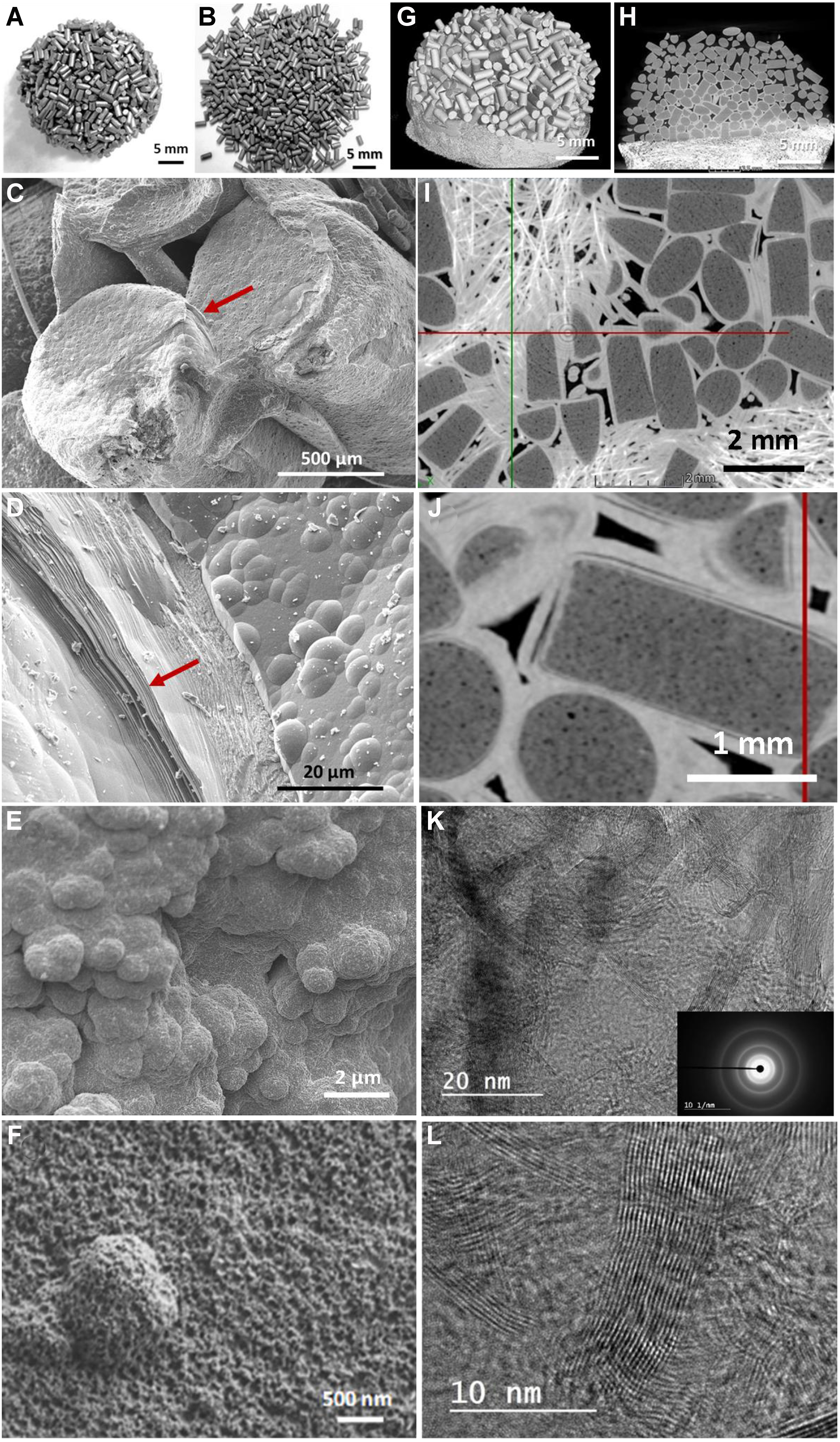
Figure 4. Digital photos of the carbon-based catalysts, R0 and R1, after reaction under (A) IH and (B) JH mode showing the difference in morphology: highly connected and loosely connected shape; (C and D) SEM micrographs of the spent IH catalyst showing the presence of graphene-like sheets within the deposited layer which acts as a solid glue for connecting the different extrudates together (indicated by arrows in C and D); (E and F) SEM micrographs of the spent JH catalyst showing a nodular carbon deposit on the catalyst surface with loose structure; (G) CT micrograph of the spent IH catalyst with stacked macroscopic shape; (H) Low magnification CT along YZ cross-section view showing the deposited graphene-like layer (with bright contrast) on the surface of the carbon catalyst; (I and J) High-magnification CT micrographs showing the homogeneous and connected structure between the deposited graphene-like layers on the surface of the carbon particles; (K and L) Corresponding TEM micrographs of the spent IH catalyst with loosely oriented graphitic planes. IH: Induction heating; JH: Joule heating; SEM: scanning electron microscopy; CT: computed tomography; TEM: transmission electron microscopy.


