fig14

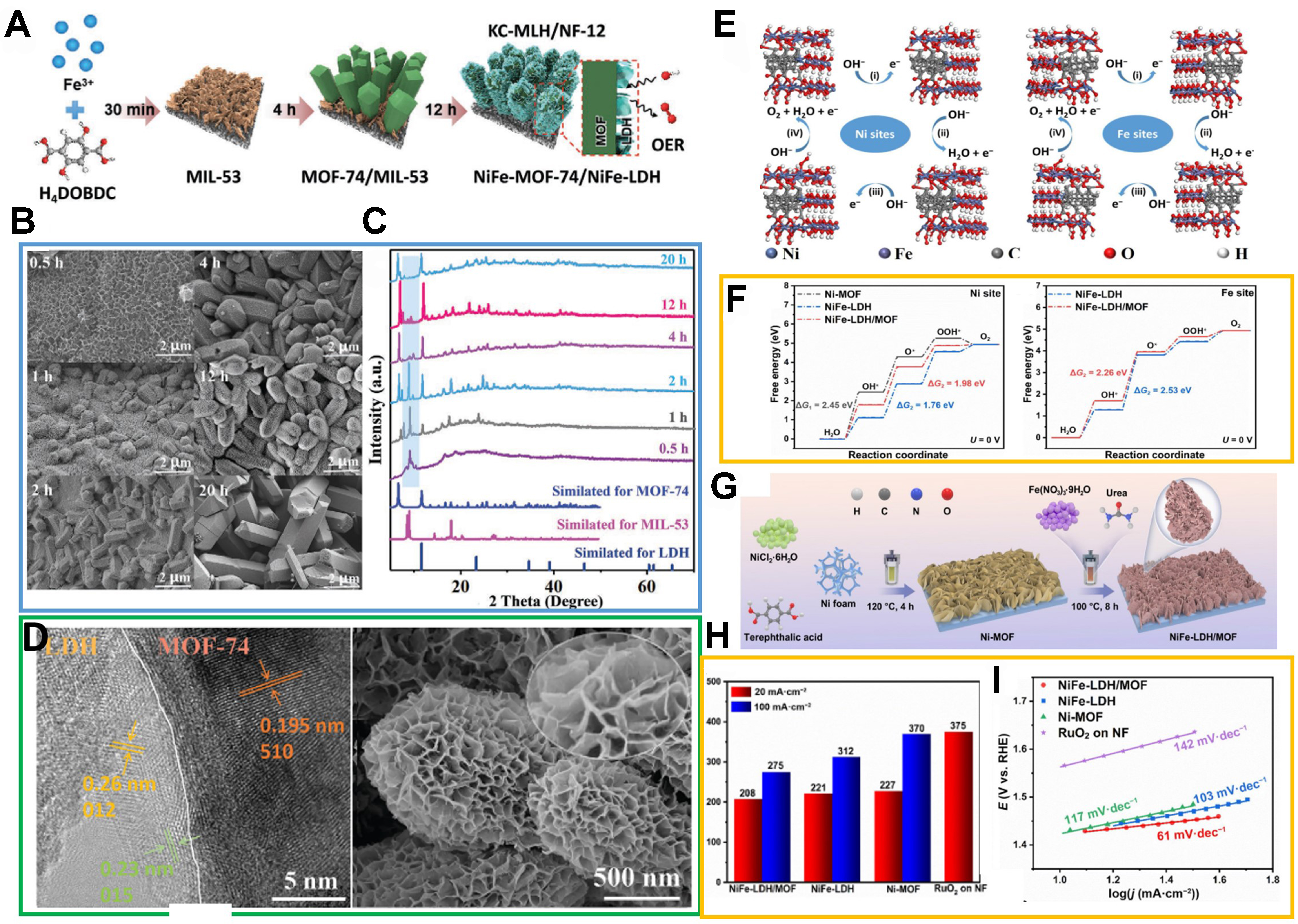
Figure 14. (A) Schematic illustration of structural evolution during kinetic-oriented formation of KC-MLH/NF-12 electrodes with different reaction times; (B) SEM images of heterostructures obtained from 0.5, 1, 2, 4, 12, and 20 h reactions; (C) corresponding XRD patterns in comparison with simulated standard references; (D) TEM images of KC-MLH/NF-12 and corresponding HRTEM image. (A)-(D) were reproduced with permission[121]. Copyright 2023, Wiley-VCH; (E) Four-electron mechanism of OER on Ni sites and Fe sites in NiFe-LDH/MOF models; (F) Calculated free-energy diagram of OER intermediates at zero potential for different models; (G) Schematic illustration of construction for NiFe-LDH/MOF nanosheet array on NF substrate; (H) Overpotential diagram (@20 and 100 mA·cm-2) corresponding to the polarization curves of OER; (I) Tafel slope plots. (E)-(I) were reproduced with permission[122]. Copyright 2023, Springer. KC-MLH: Kinetic-controlled MOF-LDH heterojunctions; NF: nickel foam; SEM: scanning electron microscope; XRD: X-ray diffraction; TEM: transmission electron microscopy; HRTEM: high-resolution transmission electron microscopy; OER: oxygen evolution reaction; LDH: layered double hydroxide; MOF: metal-organic framework.


